(1) Definition of lead-free:
In the entire electronic product, the mass percentages of the six substances Pb, Hg, Cd, hexavalent Cr, PBB (hexabromobiphenyl) and PBDE (polybrominated diphenyl ether) are 0.1%. [Note] The 0.1% mass percentage is not 0.1% of the total product mass, but 0.1% of the coating mass.
(2) Definition of lead-free solder alloy:
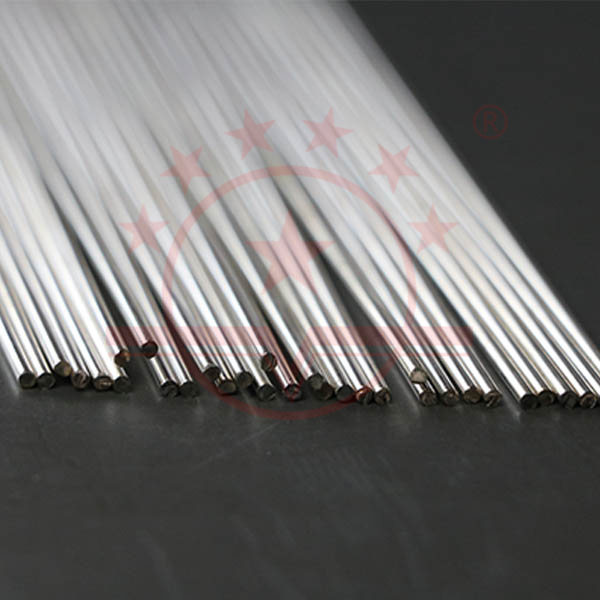
Lead-free solder is not without lead, because there is no 100% pure metal in the world, so lead-free solder refers to the upper limit of lead content in solder. The ISO045 3, JIZ328 3, and ROHS directives all require that the lead content in the alloy be 0.1%. Because lead-free solder is used in the ROHS directive, lead-free solders also require that the upper limit of the content of several other harmful substances must also meet the ROHS standard.
Temperature curve change
Lead-free solders have a high melting point, usually around 217 ° C. This will cause problems such as easy solder oxidation and rapid growth of intermetallic compounds.
The poor wetting properties of the solder can easily lead to related properties, such as the self-calibration ability, tensile strength and shear strength of the product solder joint.
Lead-free reliability issues
Relevant research shows that 70% of electronic device failures are caused by package and assembly failures. Among package and assembly failures, lead-free solder joint failure is the main cause. Its quality and reliability largely determine the quality of electronic products.
Reflow temperature curve of SMT under lead-free conditions Note: The dashed curve is suitable for processes with special requirements for solder joint brightness
The drastic reduction of the process window presents a huge challenge to ensure the quality of the weld. The drastic reduction of the process window presents a huge challenge to ensure the quality of the weld. It also brings more stability to the stability and reliability of lead-free soldering equipment. High standard. Because the device itself has a lateral temperature difference, higher requirements are imposed. Because the device itself has a lateral temperature difference, plus the original electronic device due to the difference in thermal capacity, the temperature difference will also occur during the heating process, so the temperature difference can be adjusted in the control of the lead-free reflow process. It has become very small. This is the real difficulty with lead-free reflow. This is the real difficulty with lead-free reflow.
Many problems in lead-free production
Solder and components
Lead-free solder and lead-containing solder have different melting surface tensions, different melting temperatures, and different oxidation characteristics. Lead-free solder has a higher melting point, which places higher demands on the heat resistance of the device and the PCB. The overall heat resistance of the device will also be an important consideration. Since the melting point of lead-free solders is usually much higher than that of lead-containing solders, this means that the temperature will rise significantly during the soldering process. Equipment used in leaded technology may not be able to withstand this elevated temperature (in fact, leaded technology equipment is not guaranteed to withstand lead-free temperatures, so many materials cannot withstand this high temperature). Therefore, in addition to solder materials that must be lead-free and compatible with the lead-free solder used, materials such as equipment body packaging must be able to withstand the required soldering heat energy (ie, temperature and time). Currently, lead-free and lead-containing mixtures are also very serious. Because lead-free and lead-containing materials are not completely compatible, it will lead to insufficient temperature resistance, poor solder joints, "lead contamination" and production costs.


 sales@welding-material.com


